GCP Install Guide
Introduction
Ultima Enterprise(UE) is a turn-key kubernetes solution for on-prem and cloud environment with the world class storage and networking services.
This document will guide you through the deployment of UE cluster on Google Cloud Platform(GCP) using the script.
Key Concepts and Terms
Installation only node: This is the Linux based machine from where the installation script is run. This is the machine where the installation script is copied or downloaded. This node is not a resource of GCP.
Bastion Host or Jump Server: This is the VM instance created in cloud by the installation script and used to run kubectl and dctl commands. This is created only if the user provides the option to the script to create it.
Installation and Management node: This is the VM which is configured in cloud to run the installation script and gcloud, kubectl and dctl commands. If this is used, there is no need of Installation node and Bastion host.
Nodes:The GCP virtual machine instances which are configured as Diamanti Kubernetes cluster’s master/worker nodes.
Load Balancer: This is the load balancer created to provide a Virtual IP address or VIP for Diamanti cluster
Cluster VIP: This is the IP of the load balancer configured as virtual IP address of a cluster.
Architecture
There are different options based on the combinations of the components above to configure Ultima Enterprise on GCP.
Using Installation and Management node with internal network and static routing
Using Installation and Management node with internal network and Kubernetes Load Balancer service
Using Installation only node and bastion host with internal network and Kubernetes Load Balancer service
Using Installation only node and external network
Method 1: Using Installation and Management node with internal network and static routing
In this option, Installation and Management node in cloud is used to create cluster and the cluster nodes are configured in an internal or private network. This option does not support creating Kubernetes service of type Load Balancer. To communicate with the applications running in Kubernetes cluster, a static route configuration is required.
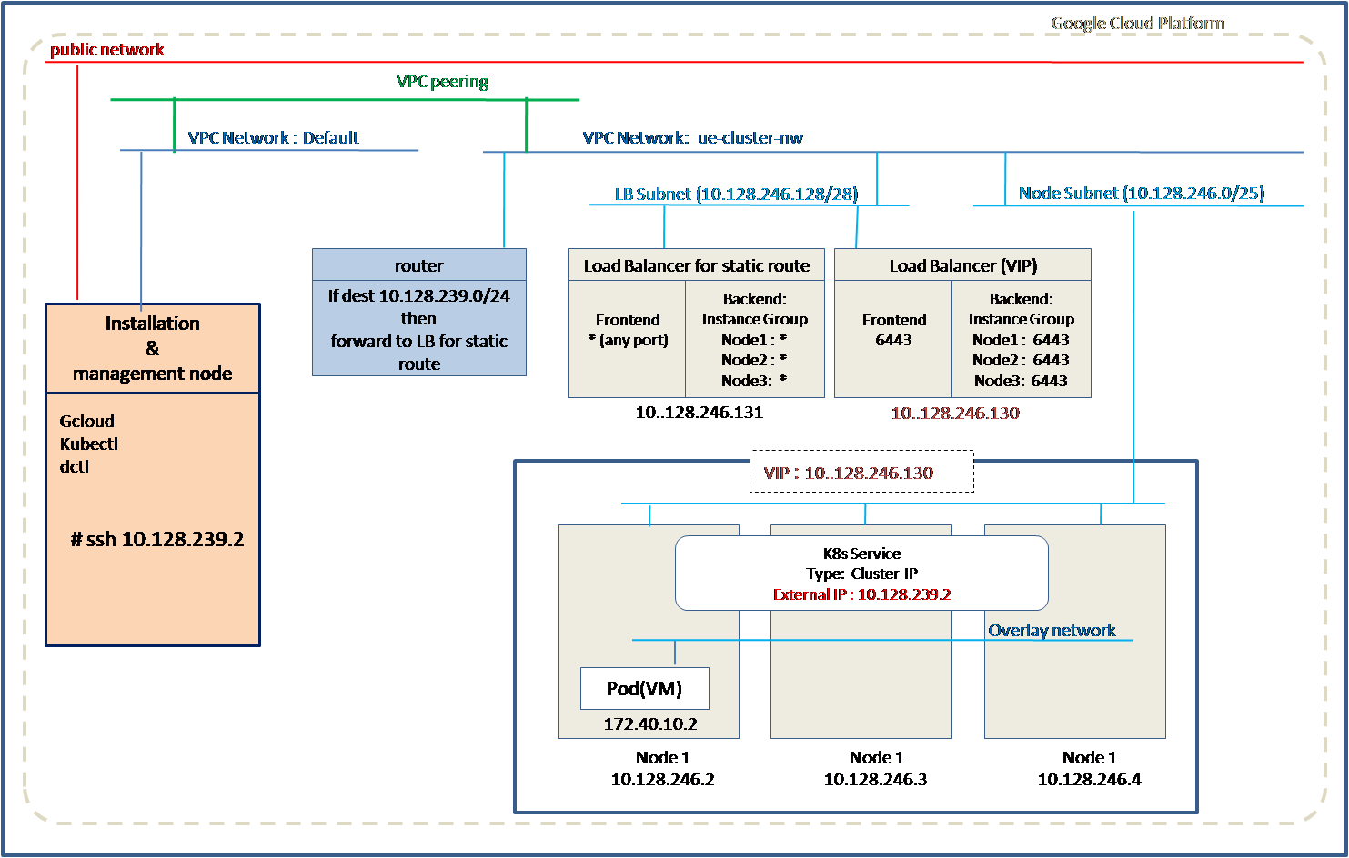
Installation and Management node is a linux machine that needs to be installed in GCP cloud before creating the cluster. Installation and Management node is connected to VPC network Default.
The installation script creates cluster nodes, load balancer, routing and forwarding rules in another VPC network. Optionally installation script can create VPC network, subnets, routes if are not already created.
The nodes are assigned IP addresses from one subnet and Load Balancer is assigned IP address from the other subnet.
A VPC peering is required between the VPC network Default and VPC network for cluster nodes(Eg. ue-cluster-nw). If VPC network does not exist, VPC peering can be created using the installation script.
A static route is configured in the VPC network to forward the incoming traffic to Load Balancer installed for static routing. The Load Balancer then forwards traffic to the cluster nodes on a specified port.
A kubernetes service of type Cluster IP can be configured. An IP from range of static route range can be used to configure in the service as External IP.
Method 2: Using Installation and Management node with internal network and Kubernetes Load Balancer service
In this option, Installation and Management node in cloud is used to create cluster and the cluster nodes are configured in an internal or private network. This option supports creating Kubernetes service of type Load Balancer with public IP address which allows external client applications to communicate with the applications running in Kubernetes cluster.
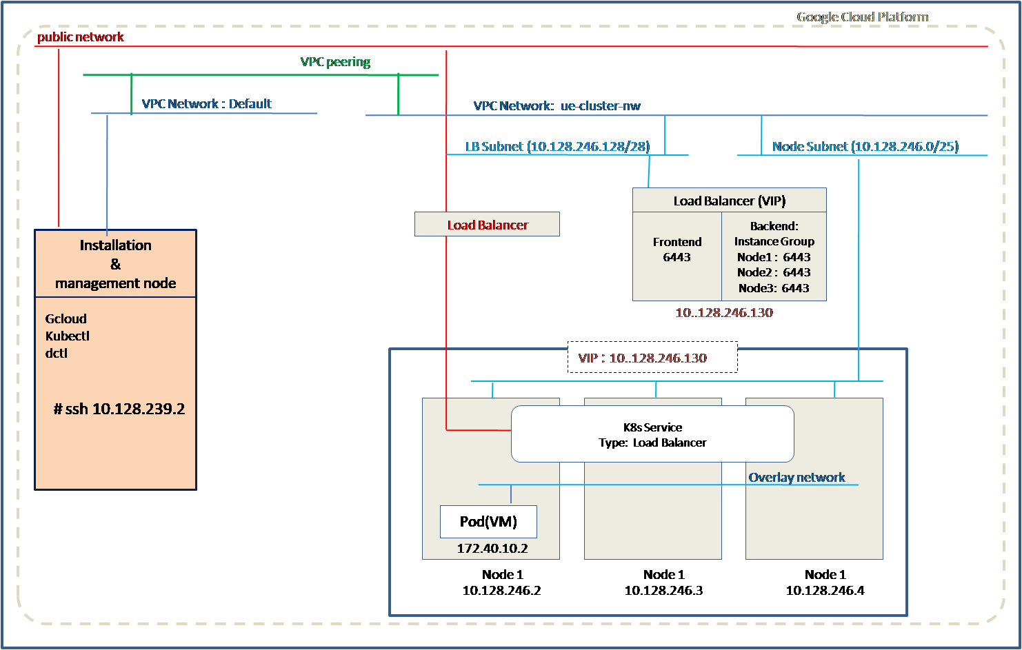
Installation and Management node is a linux machine that needs to be installed in GCP cloud before creating the cluster. Installation and Management node is connected to VPC network Default.
The installation script creates cluster nodes, load balancer, routing and forwarding rules in another VPC network. Optionally installation script can create VPC network, subnets, routes if are not already created.
The nodes are assigned IP addresses from one subnet and Load Balancer is assigned IP address from the other subnet.
A VPC peering is required between the VPC network Default and VPC network for cluster nodes(Eg. ue-cluster-nw). If VPC network does not exist, VPC peering can be created using the installation script.
A kubernetes service of type Load Balancer can be configured. A public IP address is assigned to this service which is the IP address of the Load Balancer.
Method 3: Using Installation only node and bastion host with internal network and Kubernetes Load Balancer service
In this option, Installation only node is used to create cluster and the cluster nodes are configured in an internal or private network. This option supports creating Kubernetes service of type Load Balancer with public IP address which allows external client applications to communicate with the applications running in Kubernetes cluster.
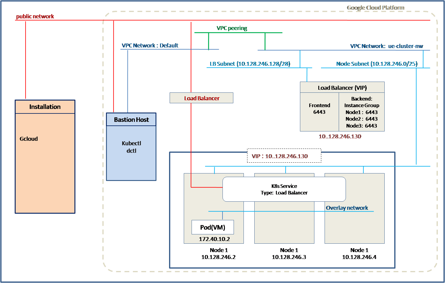
Installation only node is a linux machine that is created outside GCP cloud. This machine is used to run the installation script.
The installation script creates bastion host(Jump server), cluster nodes, load balancer, routing and forwarding rules in another VPC network. Optionally installation script can create VPC network, subnets, routes if are not already created.
The nodes are assigned IP addresses from one subnet and Load Balancer is assigned IP address from the other subnet.
A VPC peering is required between the VPC network Default and VPC network for cluster nodes(Eg. ue-cluster-nw). If VPC network does not exist, VPC peering can be created using the installation script.
A kubernetes service of type Load Balaner can be configured. A public IP address is assigned to this service which is the IP address of the Load Balancer.
Method 4: Using Installation only node with external network
In this option, Installation only node is used to create cluster and the cluster nodes are configured in an external network. All the nodes and Load Balancers will be assigned external or public addresses. This option supports creating Kubernetes service of type Load Balancer with public IP address which allows external client applications to communicate with the applications running in Kubernetes cluster.
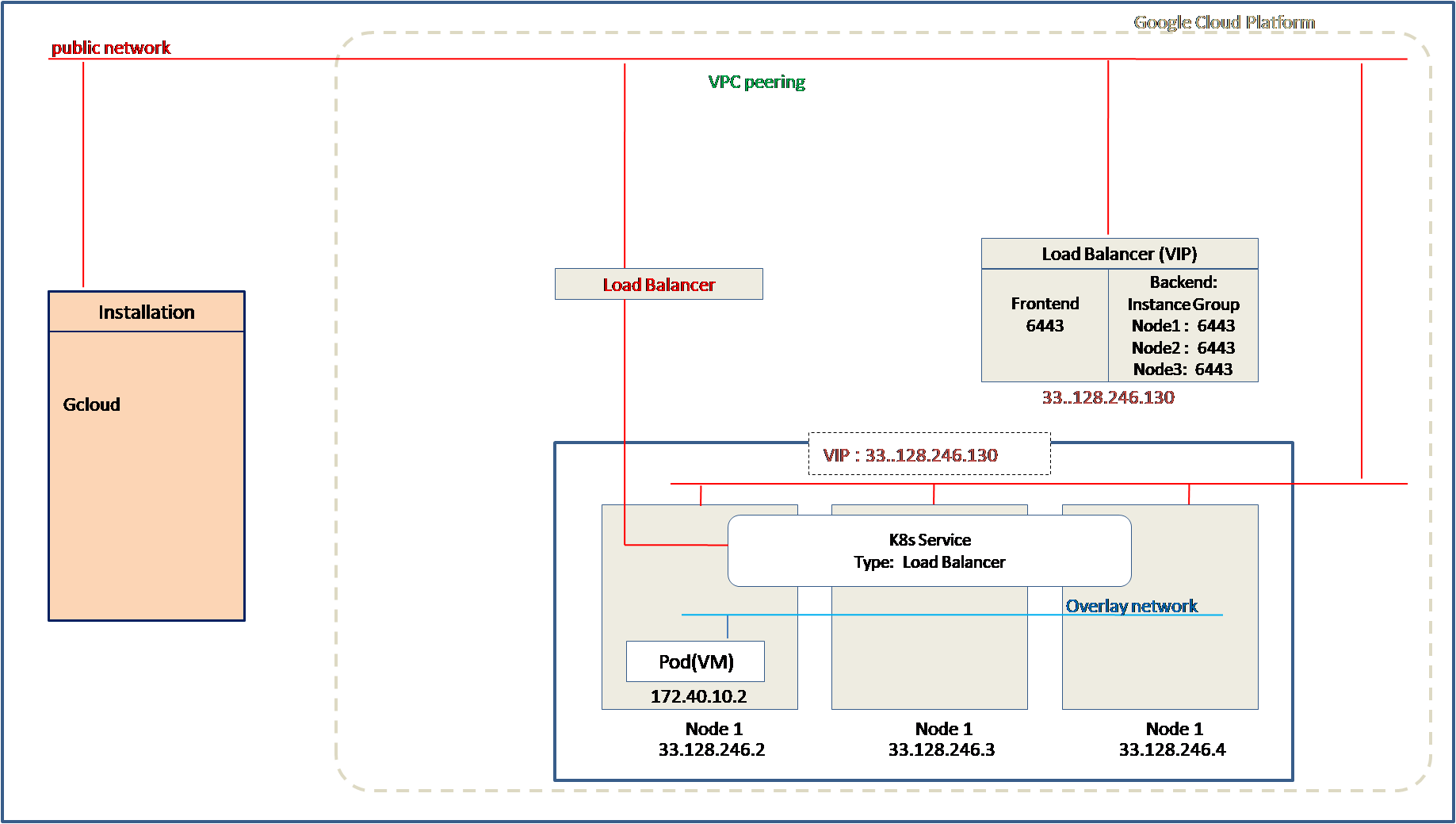
Installation only node is a linux machine that is created outside GCP cloud. This machine is used to run the installation script.
The installation script creates cluster nodes, load balancer with the external IP addresses.
A kubernetes service of type Load Balaner can be configured. A public IP address is assigned to this service which is the IP address of the Load Balancer.
Supported GCP machine types
Currently the below machine types are supported to create instances as nodes in the cluster. So it is important to select the right GCP region where these machine types are available.
n1-highmem-32 (vCPU:32, Memory:208G)
n1-standard-32 (vCPU:32, Memory:120G)
Supported Regions
This section lists the supported GCP regions for the Diamanti 3.6.2 release.
us-central1 |
europe-central2 |
asia-east1 |
asia-southeast1 |
us-east1 |
europe-north1 |
asia-east2 |
asia-southeast2 |
us-east4 |
europe-west1 |
asia-northeast1 |
australia-southeast1 |
us-west1 |
europe-west2 |
asia-northeast2 |
australia-southeast2 |
us-west2 |
europe-west3 |
asia-northeast3 |
northamerica-northeast1 |
us-west3 |
europe-west4 |
asia-south1 |
northamerica-northeast2 |
us-west4 |
europe-west6 |
asia-south2 |
southamerica-east1 |
Prerequisites
Ensure the following prerequisites are ready/installed before you deploy UE on GCP. Following prerequisites are for all the methods.
Method 1: Using Installation and Management node with internal network and static routing
Installation and Management Node running Linux (Desktop or Server based). This node should be connected to VPC network Default.
Run the command ssh-keygen with the default values or specify the path of the key pair in the json file after logging in with your user account.
$ ssh-keygen
GCP VM image (For example, ultima-enterprise-3.6.2-*) of UE is already uploaded to GCP image repository.
Copy/Download the package ue-cloud.tar.gz and untar it. Please contact Diamanti Support at support@diamanti.com to copy or download the package.
Python 3.8 or above version is installed.
GCloud SDK version 399 or above is installed on the system. (For more information, see Install the gcloud CLI.
GCP project ID
If VPC network is already created with two subnets, one for Load Balancer and one for nodes. The details of the same are required:
Network name
Load Balancer subnet name
Load Balancer subnet range
Load Balancer Region
Cluster nodes Subnet name
Cluster nodes subnet range
Cluster nodes Region
VPC peering is created between the VPC network by default and the VPC network of nodes and Load Balancers.
If there is no existing network that needs to be created, then follow instruction in the section
Network/Subnet creation [Internal] to create network and subnets.
VPC Peering creation [Internal] to create VPC peering between VPC network Default and the VPC network of nodes and Load Balancers
Following access is required in firewall.
Source |
Destination |
Port |
|---|---|---|
Installation & Management node subnet |
Load Balancer(VIP) subnet |
443, 6443, 5443, 5080, 10901 |
Installation & Management node subnet |
Cluster node subnet |
22 |
Cluster node subnet |
Load Balancer(VIP) subnet |
80, 443, 6443, 7443, 12346, 12345, 32000 |
Load Balancer(VIP) subnet |
Cluster node subnet |
80, 443, 6443, 7443, 12346, 12345, 32000, 22, 53 |
Cluster node subnet |
Cluster node subnet |
All ports |
Load Balancer(VIP) subnet |
Load Balancer(VIP) subnet |
All ports |
Static route range |
Load Balancer(VIP) subnet |
All ports |
Resource requirements per cluster
Resources |
Quota |
Type |
|---|---|---|
Static IPs(Load balancer) |
3 |
NA |
Static IPs(Nodes) |
Number_nodes * 1 |
Internal |
Backend service |
3 |
Regional Internal |
Managed Instance groups |
2 |
NA |
Forwarding rules |
4 |
Global access internal TCP Loadbalancer |
CPU |
Number_nodes * 32 |
n1-highmem-32, n1-standard-32 |
Disk(OS) |
Number_nodes *(200 + 16) |
Persistent disk (BALANCED) |
Disk |
4 * Number_nodes |
Local SSD NVME, size is 375GB for each SSD |
Health Check |
1 |
|
Network |
1 |
|
Subnetwork |
2 |
|
Instance Template |
1 |
|
Static route |
1 |
Method 2: Using Installation and Management node with internal network and Kubernetes Load Balancer service
Installation and Management Node running Linux. This node should be connected to VPC network Default.
Use your user name to log in and run the
ssh-keygencommand with the default values or specify the path of the key pair in the json file.GCP VM image (For example, ultima-enterprise-3.6.2-*) of UE is already uploaded to GCP image repository.
Copy/Download the package ue-cloud.tar.gz and untar it. Please contact Diamanti Support at support@diamanti.com to copy or download the package.
Python3.8 or above version is installed.
GCloud SDK version 399 or above is installed on the system. (For more information, see Install the gcloud CLI.
GCP project name
If VPC network is already created with two subnets, one for Load Balancer and one for nodes. The details of the same are required:
Network name
Load Balancer subnet name
Load Balancer subnet range
Load Balancer Region
Cluster nodes Subnet name
Cluster nodes subnet range
Cluster nodes Region
VPC peering is created between the VPC network Default and the VPC network of nodes and Load Balancers.
If there is no existing network and needs to be created, then follow instruction in the section
Network/Subnet creation[Internal] below to create network and subnets.
VPC Peering creation [Internal] below to create VPC peering between VPC network Default and the VPC network of nodes and Load Balancers
Following access is required in firewall.
Source |
Destination |
Port |
|---|---|---|
Installation & Management node subnet |
Load Balancer(VIP) subnet |
443, 6443, 5443, 5080, 10901 |
Installation & Management node subnet |
Cluster node subnet |
22 |
Cluster node subnet |
Load Balancer(VIP) subnet |
80, 443, 6443, 7443, 12346, 12345, 32000 |
Load Balancer(VIP) subnet |
Cluster node subnet |
80, 443, 6443, 7443, 12346, 12345, 32000, 22, 53 |
Cluster node subnet |
Cluster node subnet |
All ports |
Load Balancer(VIP) subnet |
Load Balancer(VIP) subnet |
All ports |
Status route range |
Load Balancer(VIP) subnet |
All ports |
Resource requirements per cluster
Resources |
Quota |
Type |
|---|---|---|
Static IPs(Load balancer) |
3 |
NA |
Static IPs(Nodes) |
Number_nodes * 1 |
Internal |
Backend service |
3 |
Regional Internal |
Managed Instance groups |
2 |
NA |
Forwarding rules |
4 |
Global access internal TCP Loadbalancer |
CPU |
Number_nodes * 32 |
n1-highmem-32, n1-standard-32 |
Disk(OS) |
Number_nodes *(200 + 16) |
Persistent disk (BALANCED) |
Disk |
4 * Number_nodes |
Local SSD NVME, size is 375GB for each SSD |
Health Check |
1 |
|
Network |
1 |
|
Subnetwork |
2 |
|
Instance Template |
1 |
|
Static route |
1 |
Resource requirements for K8s Loadbalancer service
Resources |
Quota |
Type |
|---|---|---|
Global/External IP |
1 |
NA |
Forwarding Rules |
1 |
External Load balancer |
Targetpool |
1 |
NA |
Firewall Rule |
1 |
NA |
Health Check |
1 |
NA |
For egress traffic to work for external IP assigned for Kubernetes load balancer service follow the instruction in the section Router and Nat.
Method 3: Using Installation only node and bastion host with internal network and Kubernetes Load Balancer service
Installation only node outside GCP running Linux. This is not a GCP resource.
Use your user name to log in and run the
ssh-keygencommand with the default values or specify the path of the key pair in the json file..$ ssh-keygen
GCP VM image (For example, ultima-enterprise-3.6.2-*) of UE is already uploaded to GCP image repository.
Copy/Download the package ue-cloud.tar.gz and untar it on the Linux system. Please contact Diamanti Support at support@diamanti.com to copy or download the package.
Python3.8 or above version is installed.
GCloud SDK version 399 or above is installed on the system. (For more information, see Install the gcloud CLI.
GCP project name
If VPC network is already created with two subnets, one for Load Balancer and one for nodes. The details of the same are required:
Network name
Load Balancer subnet name
Load Balancer subnet range
Load Balancer Region
Cluster nodes Subnet name
Cluster nodes subnet range
Cluster nodes Region
VPC peering is created between the VPC network Default and the VPC network of nodes and Load Balancers.
If there is no existing network and needs to be created, then follow instruction in the section
Network/Subnet creation[Internal] below to create network and subnets.
VPC Peering creation [Internal] below to create VPC peering between VPC network Default and the VPC network of nodes and Load Balancers
Following access is required in firewall.
Source |
Destination |
Port |
|---|---|---|
Installation & Management node subnet |
Load Balancer(VIP) subnet |
443, 6443, 5443, 5080, 10901 |
Installation & Management node subnet |
Cluster node subnet |
22 |
Cluster node subnet |
Load Balancer(VIP) subnet |
80, 443, 6443, 7443, 12346, 12345, 32000 |
Load Balancer(VIP) subnet |
Cluster node subnet |
80, 443, 6443, 7443, 12346, 12345, 32000, 22, 53 |
Cluster node subnet |
Cluster node subnet |
All ports |
Load Balancer(VIP) subnet |
Load Balancer(VIP) subnet |
All ports |
Status route range |
Load Balancer(VIP) subnet |
All ports |
Resource requirements per cluster
Resources |
Quota |
Type |
|---|---|---|
Static IPs(Load balancer) |
3 |
NA |
Static IPs(Nodes) |
Number_nodes * 1 |
Internal |
Backend service |
3 |
Regional Internal |
Managed Instance groups |
2 |
NA |
Unmanaged Instance group |
1 |
NA |
Forwarding rules |
4 |
Global access internal TCP Loadbalancer |
CPU |
Number_nodes * 32 |
n1-highmem-32, n1-standard-32 |
CPU(bastion node) |
2 |
n1-standard-2 |
Disk(OS) |
Number_nodes *(200 + 16) |
Persistent disk (BALANCED) |
Disk |
4 * Number_nodes |
Local SSD NVME, size is 375GB for each SSD |
Disk(bastion node) |
(200 + 16) |
Persistent disk (BALANCED) |
Health Check |
1 |
|
Network |
1 |
|
Subnetwork |
2 |
|
Instance Template |
1 |
|
Static route |
1 |
Resource requirements for K8s Loadbalancer service
Resources |
Quota |
Type |
|---|---|---|
Global/External IP |
1 |
NA |
Forwarding Rules |
1 |
External Load balancer |
Targetpool |
1 |
NA |
Firewall Rule |
1 |
NA |
Health Check |
1 |
NA |
For egress traffic to work for external IP assigned for Kubernetes load balancer service follow the instruction in the section Router and Nat below
Method 4: Using Installation only node and external network
Installation only node outside GCP running Linux. This is not a GCP resource.
Use your user name to log in and run the
ssh-keygencommand with the default values or specify the path of the key pair in the json file.$ ssh-keygen
GCP VM image (eg. ultima-enterprise-3.6.2-*) of UE is already uploaded to GCP image repository.
Copy/Download the package ue-cloud.tar.gz and untar it on the Linux system. Please contact Diamanti Support at support@diamanti.com to copy or download the package.
Python3.8 or above version is installed.
GCloud SDK version 399 or above is installed on the system. (For more information, see Install the gcloud CLI.
GCP project name
Following access is required in firewall.
Source |
Destination |
Port |
|---|---|---|
Installation & Management node subnet |
Load Balancer(VIP) subnet |
443, 6443, 5443, 5080, 10901 |
Installation & Management node subnet |
Cluster node subnet |
22 |
Cluster node subnet |
Load Balancer(VIP) subnet |
80, 443, 6443, 7443, 12346, 12345, 32000 |
Load Balancer(VIP) subnet |
Cluster node subnet |
80, 443, 6443, 7443, 12346, 12345, 32000, 22, 53 |
Cluster node subnet |
Cluster node subnet |
All ports |
Load Balancer(VIP) subnet |
Load Balancer(VIP) subnet |
All ports |
Status route range |
Load Balancer(VIP) subnet |
All ports |
Resource requirements per cluster
Resources |
Quota |
Type |
|---|---|---|
Static IPs |
Number_nodes * 1 |
Internal |
Global IP/External |
Number_nodes * 1 |
NA |
Backend service |
1 |
Regional External |
Managed Instance groups |
2 |
NA |
Forwarding rules |
2 |
External TCP Load balancer |
CPU |
Number_nodes * 32 |
n1-highmem-32, n1-standard-32 |
Disk(OS) |
Number_nodes *(200 + 16) |
Persistent disk (BALANCED) |
Disk |
4 * Number_nodes |
Local SSD NVME, size is 375GB for each SSD |
Health Check |
1 |
|
Instance Template |
1 |
Resource requirements for K8s Loadbalancer service
Resources |
Quota |
Type |
|---|---|---|
Global/External IP |
1 |
NA |
Forwarding Rules |
1 |
External Load balancer |
Targetpool |
1 |
NA |
Firewall Rule |
1 |
NA |
Health Check |
1 |
NA |
Network Configuration
Below are the sections to create VPC network, subnets, VPC peering, NATing, routing, etc which is required if there is no existing network configured.
Network/Subnet creation [Internal]
For the internal/private network type, user needs to create the VPC network, Load Balancer(LB) subnet and node subnet, vpc-peering between user defined network and GCP default network.
Only one network and two subnets is supported for internal network type.
Network creation:
Internal networks should have subnet mode set to custom so that you can configure subnet ranges.
"network": {
   "name": "network-name",
   "subnet_mode": "custom",
   "project_id": "changeme"
}
Subnet creation:
Following section in the json file is for subnet creation. Subnet 10.128.0.0/20 is reserved for default network. We have to choose subnet which does not overlap any subnet created in VPC.
Choose range 10.128.250.0/24 for your network, then divide this range into two subnets
10.128.250.0/25 for node subnet and 10.128.250.128.0/28 for load balancer subnet.
The subnet will be created under network which was given in the network creation details.
Note: enable-google-private-ip=true is required for kubernetes load balancer service to work. Here we are creating private subnetworks and google api server is not accessible until we enable this flag. So if we do not enable this flag load balancer service would not get external IP.
"subnet": [
   {
      "name": "lb-subnet-name",
      "range": "10.128.250.128/28",
      "region": "us-central1",
      "enable-google-private-ip": "true"
   },
   {
      "name": "node-subnet-name",
      "range": "10.128.250.0/25",
      "region": "us-central1",
      "enable-google-private-ip": "true"
   }
]
- The network.json looks like below and it can be used to create network and subnets.Same json can be used to delete subnets and network. First we need to delete subnets and then network.
{
"network": {
   "name": "network-name",
   "subnet_mode": "custom",
   "project_id": "changeme"
},
"subnet": [
   {
      "name": "lb-subnet-name",
      "range": "10.128.250.128/28",
      "region": "us-central1",
      "enable-google-private-ip": "true"
   },
   {
      "name": "node-subnet-name",
      "range": "10.128.250.0/25",
      "region": "us-central1",
      "enable-google-private-ip": "true"
   }
]
}
To create/delete the network and subnet refer the usage of the commands below:
$ python3.8 gcp_deploy.py --config-json-file config_json/network.json --command add-network
$ python3.8 gcp_deploy.py --config-json-file config_json/network.json --command add-subnet
$ python3.8 gcp_deploy.py --config-json-file config_json/network.json --command del-subnet
$ python3.8 gcp_deploy.py --config-json-file config_json/network.json --command del-network
Router/Nat creation
Router/Nat provides source network address translation for interfaces without external ip address. You can configure it for certain ip addresses or a subnet range. This could be used in scenario where user wants the node in internal network want to access nodes outside VPC with external IP.
The internal/private network type requires the creation of a VPC network, a Load Balancer(LB) subnet, and a node subnet, as well as vpc peering between the user defined network and GCP’s default network.
You can create only one router and NAT. Google Cloud advertises the range through a router.
2. With custom_advertising_ranges, you can add the custom IP ranges that needs source network address translation.
3. With advertising_group, you can advertise all the subnets in the network , If you use advertising group right now it supports only one value “all_subnets” , which advertises all the subnets in a given network. This is not recommended if you do not want to advertise all the subnets in network instead you could use custom_advertising_ranges.
"router": {
   "project_name": "<project id>",
   "name": "router-name",
   "region": "region",
   "network": "network-name",
   "advertising_mode": "custom",
   "custom_advertising_ranges": "<node-subnet-range>"
}
Nat creation:
Following section in the json file is for NATncreation.
nat_external_ip_pool can be set to auto or you can specify already reserved external ip address comma separated list.
Nat_subnet_ip_ranges here you can specify all subnets using the value “all” or could specify subnet names in a comma separated list.
Note
There is no support for updating the subnet list in a router and creating a NAT. In order to update the list del, a router and NAT resource were created with the updated list.
"nat": {
   "name": "<nat-name>",
   "nat_external_ip_pool": "auto",
   "nat_subnet_ip_ranges": "<node-subnet-name>"
}
The Example router.json can be used to create routers and nats, and the same json can be used to delete routers and nat.
{
"router": {
   "project_name": "<project-id>",
   "name": "router-name",
   "region": "us-east1",
   "network": "network-name",
   "advertising_mode": "custom",
   "custom_advertising_ranges": "node-subnet-range <node subnet range where range is 10.128.250.0/25>"
},
"nat": {
   "name": "nat-name",
   "nat_external_ip_pool": "auto",
   "nat_subnet_ip_ranges": "node-subnet-name <node subnet name where range is 10.128.250.0/25>"
}
}
Please refer to the following commands for creating/deleting the routers and NATs:
$ python3.8 gcp_deploy.py --config-json-file config_json/router.json --command add-router

$ python3.8 gcp_deploy.py --config-json-file config_json/router.json --command add-nat

$ python3.8 gcp_deploy.py --config-json-file config_json/router.json --command del-router

$ python3.8 gcp_deploy.py --config-json-file config_json/router.json --command del-nat
VPC Peering creation [Internal]
The custom subnets created in the section above cannot be communicated from other network as they are private. Using VPC peering, two networks can be connected for communication. For example, if two networks default and network-name are peered, then custom network “network-name” can be accessed from the default network. The default network is accessible from outside.
In the following example, default network and custom network network-name are confiured as peers in the file peer_network.json
{
"peer_network": [
   {
      "network_name": "network-name",
      "peer_network_name": "default",
      "project_id": "changeme"
   }
]
}
Same json can be used to delete VPC peering. It is recommended to delete VPC peering first and then subnets and networks.
RUn the following command to create or delete the VPC peering.
$ python3.8 gcp_deploy.py --config-json-file config_json/peer_network.json --command create-vpc-peering

$ python3.8 gcp_deploy.py --config-json-file config_json/peer_network.json --command del-vpc-peering
Installation
Depending on the installation method, follow the steps to create the UE cluster on GCP.
Login to the Gcloud CLI (Reference link: (For more information, see Install the gcloud CLI.
$ gcloud init
Extract the ue-cloud package.
$ tar -zxvf ue-cloud.tar.gz
Open the gcp directory.
$ cd gcp
The config_json directory contains all the necessary json files.
See the usage of the gcp deploy script.
$ python3.8 gcp_deploy.py -h

usage: gcp_deploy.py [-h] [--config-json-file config_json_file]
                  [--command command_name] [--preinstall-dir pre_dir_path]
                  [--postinstall-dir post_dir_path] [--spot-type spot_type]
                  [--get-cluster-info cluster_name]

Get the infrastructure and Kubernetes input from a JSON file and perform the given operations.

optional arguments:
-h, --help            show this help message and exit
--config-json-file config_json_file
                        JSON file path [infra/Kubernetes configuration JSON, network JSON file path, peer network JSON file path]
--command command_name
                        Define command [create-infra, destroy-infra, add-node, remove-node, add-network, add-subnet, create-vpc-peering, add-router, del-router, add-nat, del-nat, del-network, del-subnet, del-vpc-peering, create-cluster, attach-node]
--preinstall-dir pre_dir_path
                        Directory path which has RPM and install script
--postinstall-dir post_dir_path
                        Directory path which has install script
--spot-type spot_type
                        Define Spot Type [preemptible, spot, ondemand]
--get-cluster-info cluster_name
                        Cluster name to get the cluster info
Method 1: With internal network and static routing
To create the cluster without public IP address(internal network), use the internal_network_infra_k8s_conf.json file located at gcp/config_json and update the required fields. Below is the example of internal_network_infra_k8s_conf.json file.
This cluster will only have internal IP addresses. The fields in red indicate what needs to be configured with internal networks and static routes.
{
"infra": {
   "image_name": "https://www.googleapis.com/compute/v1/projects/sandbox-279818/global/images/ultima-enterprise-3-6-2-101",
   "project_name": "project-id",
   "enable_cloud_provider": "false",
   "network_type": "internal",
   "zones": [
      "us-central1-a",
      "us-central1-b",
      "us-central1-c"
   ],
   "machine_type": "n1-standard-32",
   "node_type": "master",
   "create_cluster": "false",
   "jump_host": "false",
   "dns_server": "<server-address>",
   "dns_search_domain": "domain name",
   "number_of_nodes": 3,
   "node_info": [
      {
      "node_name": "n1",
      "hostname": "my-name-n1.my-domain.com"
      },
      {
      "node_name": "n2",
      "hostname": "my-name-n2.my-domain.com"
      },
      {
      "node_name": "n3",
      "hostname": "my-name-n3.my-domain.com"
      }
   ],
   "authentication": {
      "sa_account": "sa-account-name",
      "ssh_public_key": "./ssh_keys/diamanti_id.pub",
      "ssh_private_key": "./ssh_keys/diamanti_id"
   },
   "network_info": {
      "network_name": "network-name",
      "lb_subnet": "lb-subnet-name",
      "node_subnet": "node-subnet-name",
      "pod_overlay_range": "172.40.0.0/16",
      "static_route_range": "10.128.231.0/24",
      "static_route_enable": "true"
   }
},
"k8s": {
   "cluster_name": "changeme"
}
}
Image_name: Diamanti image used to create instances.
project_name: Project id under which resources will be created.
enable_cloud_provider(true/false): The flag to enable or disable cloud provider service. If enabled, cloud provider services which will provision external ip when we create kubernetes load balancer service.
Network_type: Value would be
internal.number_of_nodes: Specifies the number of nodes to create a cluster. Number of nodes will be listed in node_info.
zones: List of zones to be used for nodes for this cluster. Update the zone list as per user permissions and available required CPU/Memory quotas.
node_type: Node type should be master while creatig cluster with
create-infracommand.node_name would be postfix to your cluster name provided. For example, If the cluster name is john then the node names would be john-n1, john-n2, john-n3 from the above values.
cluster_name: The name of cluster to be created.
- host_name can be configured, if it is configured for one node then
it must be configured for all nodes. DNS entry has to done by user and diamanti will not add this CNAME dns recored. This is an optional field.
Authentication is optional. By default ssh keys are used from ~/.ssh/ directory.
ssh_public_key: path of public key to be used
ssh_private_key: path of private key to be used
Sa_account: Service account to be used while creating instance. Service account determines the scope/permission of user while creating instance.
Static routes creation can be disabled using static_route_enable to false, by default it is created. This is an optional field.
Static route range is used when we want to access pod from outside the cluster, we create static route with this range whose destination can also be configured using “static_route_range” otherwise pod_overlay_range is used a static route range when enabled. For detailed description please refer “Accessing pod from outside cluster network “ section.Static_route_range is used when we want to access pod from outside the cluster and when we cannot use pod_overlay_range as static route.This range should not be overlapping with any subnet range and pod overlay range. This is an optional field.
Create_cluster can be disabled by setting it to false. In this case it will only provision the resources. We can then create cluster using create-cluster command. For add-node command we can disable attaching node to cluster using “attach-node”:”false”. Node attach can be done using same json and attach-node command. This is an optional field.
Jump_host can be set to true or false, if set to false we will not create bastion node host while creating cluster. This is set to be false only in case where VPC can be accessed from management node. This is an optional field.
dns_server is used to specify addition dns name server. This is an optional field.
dns_search_domain is used to add dns search domain to /etc/resolv.conf on every node. This is an optional field.
Machine_type is n1-highmem-32 or n1-standard-32
n1-highmem-32 (vCPU:32, Memory:208G)
n1-standard-32 (vCPU:32, Memory:120G)
pod_overlay_range: This is a subnet range for cluster pod network. This is optional. This field will be used to create static route if static_route_range is not defined. For detailed description please refer “Accessing pod from outside cluster network “ section. This range should not be overlapping with any other subnet range and pod overlay range.
network_name: Network from where ip would be assigned to cluster resources.
lb_subnet: subnet in the network specified in network_name, from where ip for load balancer would be assigned
Node_subnet: subnet in the network specified in network_name, from where ip of nodes would be assigned.
Using the
create-infracommand, create a cluster by using 3 or 5 master nodes.$ python3.8 gcp_deploy.py --config-json-file config_json/internal_network_infra_k8s_conf.json --command create-infra
The cluster/resources are created based on the
create_clusterfield in the JSON file, and the details are shown in the terminal.You can see the logs in <cluster-name>-cluster.log file while cluster creation is in progress.
- When the
cluster_createfield is set to false while running thecreate_infracommand, then only the nodes are provisioned and no cluster is created. To create cluster use the json used for provisioning the nodes and run following command to create cluster.
$ python3.8 gcp_deploy.py --config-json-file config_json/internal_network_infra_k8s_conf.json --command create-cluster
- When the
Method 2 & 3 : With internal network and K8s Load Balancer service
To create the cluster without public IP address(internal network) and the provision for K8s service of type Load Balancer, use the infra_k8s_conf.json file located at gcp/config_json and update it with the required fields. Below is the example of infra_k8s_conf.json file.
Nodes in this cluster will only get internal IP addresses. Therefore, static_route_enable must be false.
If using method 2, jump_host should be false and if using method 3 jump_host should be true.
{
"infra": {
   "image_name": "https://www.googleapis.com/compute/v1/projects/sandbox-279818/global/images/ultima-enterprise-3-6-2-101",
   "project_name": "project-id",
   "enable_cloud_provider": "true",
   "network_type": "internal",
   "zones": [
      "us-central1-a",
      "us-central1-b",
      "us-central1-c"
   ],
   "machine_type": "n1-standard-32",
   "node_type": "master",
   "create_cluster": "true",
   "jump_host": "true",
   "dns_server": "<server-address>",
   "dns_search_domain": "domain name",
   "number_of_nodes": 3,
   "node_info": [
      {
      "node_name": "n1",
      "hostname": "my-name-n1.my-domain.com"
      },
      {
      "node_name": "n2",
      "hostname": "my-name-n2.my-domain.com"
      },
      {
      "node_name": "n3",
      "hostname": "my-name-n3.my-domain.com"
      }
   ],
   "authentication": {
      "sa_account": "sa-account-name",
      "ssh_public_key": "./ssh_keys/diamanti_id.pub",
      "ssh_private_key": "./ssh_keys/diamanti_id"
   },
   "network_info": {
      "network_name": "network-name",
      "lb_subnet": "lb-subnet-name",
      "node_subnet": "node-subnet-name",
      "pod_overlay_range": "172.40.0.0/16",
      "static_route_range": "10.128.231.0/24",
      "static_route_enable": "false"
   }
},
"k8s": {
   "cluster_name": "CHANGEME"
}
}
Using the
create-infracommand, create a cluster by using 3 or 5 master nodes.$ python3.8 gcp_deploy.py --config-json-file config_json/internal_network_infra_k8s_conf.json --command create-infra
The cluster/resources are created based on the
create_clusterfield in the JSON file, and the details are shown in the terminal.You can see the logs in <cluster-name>-cluster.log file while cluster creation is in progress.
When the
cluster_createfield is set to false while running thecreate_infracommand, then only the nodes are provisioned and no cluster is created.
To create cluster use the json used for provisioning the nodes and run following command to create cluster.
$ python3.8 gcp_deploy.py --config-json-file
config_json/internal_network_infra_k8s_conf.json --command create-cluster
Method 4: With external network
In order to configure the cluster with a public IP address, use the infra_k8s_conf.json file located at gcp/config_json and update it with the required information.
In this cluster, the node will get internal as well as external IP addresses.
{
"infra": {
   "image_name": "https://www.googleapis.com/compute/v1/projects/sandbox-279818/global/images/ultima-enterprise-3-6-2-101",
   "project_name": "project-id",
   "enable_cloud_provider": "true",
   "network_type": "external",
   "zones": [
      "us-central1-a",
      "us-central1-b",
      "us-central1-c"
   ],
   "machine_type": "n1-standard-32",
   "node_type": "master",
   "number_of_nodes": "3",
   "node_info": [
      {
      "node_name": "n1"
      },
      {
      "node_name": "n2"
      },
      {
      "node_name": "n3"
      }
   ]
},
"k8s": {
   "cluster_name": "CHANGME"
}
}
Image_name: Diamanti image used to create instances
project_name: Project id under which resources will be created.
enable_cloud_provider(true/false): Do we need to enable cloud provider services which will provision external ip when we create kubernetes load balancer service. Value true enables cloud provider services and false disables it.
number_of_nodes: Number of nodes you want to create cluster with. node_info will have entries for number of nodes.
Network_type: Value would be external
Zones: List of zones to be used for nodes for this cluster
Machine_type is n1-highmem-32 or n1-standard-32
n1-highmem-32 (vCPU:32, Memory:208G)
n1-standard-32 (vCPU:32, Memory:120G)
node_type: Node type should be master while creating cluster
node name would be postfix to your cluster name provided. Eg. If the cluster name is john then the node names would be john-n1, john-n2, john-n3 from the above values.
cluster_name: The name of cluster to be created.
Using the
create-infracommand, create a cluster by using 3 or 5 master nodes.$ python3.8 gcp_deploy.py --config-json-file config_json/external_network_infra_k8s_conf.json --command create-infra
It will create the cluster and the details are shown in the terminal.
You can see the logs in <cluster-name>-cluster.log file while cluster creation is in progress and cluster info in <cluster-name>-cluster.info file after cluster creation.
Using the Cluster
Access the cluster:
To see the cluster info, you can run below command
$ python3.8 gcp_deploy.py --get-cluster-info <cluster_name>
If the cluster is created using the internal network and with jump_host is not false, then SSH to the bastion host.
$ ssh diamanti@<cluster-name>-bastion
For cluster created using jump_host: false nodes can be accessed from management node and cluster can be logged in from management node. For the cluster created using external network you can login to the cluster from any of the cluster node.
Run the cluster login command
$ dctl -s <VIP> login -u admin -p Diamanti@111
Note: For more usage, follow Diamanti Usage Guide.
Cluster deletion for GCP
To destroy the cluster use the below command with the same json file which was used while creating the cluster.
$ python3.8 gcp_deploy.py --config-json-file config_json/internal_network_infra_k8s_conf.json --command destroy-infra
Add and Remove node
Adding a Node
Add the master or worker nodes to the UE GCP cluster using following steps.
Update a**dd_remove_node_infra_k8s_conf.json**. Following is the json file.
{
"infra": {
   "image_name": "https://www.googleapis.com/compute/v1/projects/sandbox-279818/global/images/ultima-enterprise-3-6-2-101",
   "project_name": "project-id",
   "region": "us-central1",
   "node_type": "master",
   "attach_node": "true",
   "number_of_nodes": 3,
   "node_info": [
      {
      "node_name": "n1",
      "hostname": "my-name-n1.my-domain.com"
      },
      {
      "node_name": "n2",
      "hostname": "my-name-n2.my-domain.com"
      },
      {
      "node_name": "n3",
      "hostname": "my-name-n3.my-domain.com"
      }
   ],
   "authentication": {
      "sa_account": "sa-account-name",
      "ssh_public_key": "./ssh_keys/diamanti_id.pub",
      "ssh_private_key": "./ssh_keys/diamanti_id"
   }
},
"k8s": {
   "cluster_name": "changeme"
}
}
Image_name: Diamanti image used to create instances
project_name: Project id under which resources will be created.
region: Region where resources needs to be created.
node_type: Node type could be master or worker
number_of_nodes: Number of nodes you want to add to cluster. node_info will have entries for number of nodes.
node_name would be postfix to your cluster name provided. For example, if the cluster name is john then the node names would be john-n1, john-n2, john-n3 from the above values.
cluster_name: The name of cluster where node needs to be added.
host_name can be configured, if it is configured for one node during create-infra then it must be configured for all nodes. DNS entry has to done by user and diamanti will not add this CNAME dns recored. This is an optional field.
Authentication is optional. By default ssh keys are used from ~/.ssh/ directory.
ssh_public_key: path of public key to be used
ssh_private_key: path of private key to be use
Sa_account: Service account to be used while creating instance. Service account determines the scope/permission of user while creating instance.
attach_node can be disabled by setting it to “false”. In this case it will only provision the resources. Node attach can be done using same json and attach-node command. This is an optional field.
- Then run the below command to add the node to the existing cluster. Multiple nodes of one type of node can be added in the cluster.Please note, the cluster support max 5 master nodes.
$ python3.8 gcp_deploy.py --config-json-file config_json/internal_add_remove_node_infra_k8s_conf.json --command add-node
If attach_node field is set to false while running add-node command then it will only provision nodes and not attach nodes to cluster. To attach nodes to cluster use the same json used for provisioning the nodes and run following commands to attach node.
$ python3.8 gcp_deploy.py --config-json-file config_json/internal_add_remove_node_infra_k8s_conf.json --command attach-node
Removing a Node
$ python3.8 gcp_deploy.py --config-json-file config_json/internal_add_remove_node_infra_k8s_conf.json --command remove-node
Accessing pod from outside cluster network
Static route is created so that traffic with a destination ip in a destination range will be routed to the cluster. User can define destination range using static_route_range or pod_overlay_range fields while creating cluster.
It is assumed that static route destination range can be reached/routed from the node, from where user is trying to access pods of cluster.
For example management node is in default network and nodes are in VPC network diamanti-test, , static route is created in diamanti-test network with a destination range say (10.128.340.0/24). When we create vpc peering between two networks default and diamanti-test, custom routes should also be exchanged. So in this case when we access 10.128.340.0/24 range from default network it will be routed to VPC diamanti-test and hence we can access diamanti-test network from default network.
pod_overlay_range is the range used for pod network inside the cluster. If we do not specify static_route_range and static_route_enable is true then pods inside cluster can be reached from outside the cluster using pod_overlay_range.
Use case of static route range is when we do not want entire pod network to be accessed from outside the cluster or we have less number of ip address for pod network in such case we can define pod network as private range with large subnet and define static_route_range with different small subnet.
If static_route_range is defined then pods inside the cluster cannot be reached using ip in static_route_range directly. We have to use following method so that pods can be reached using static route range.
User needs to create a service for a pod so that pod can be accessed from that service. Un-used IP from static route range should be added as external ip in that service. The service type could be of nodeport or Load balancer or cluster ip.
Example command: Kubectl expose pod <pod-name> –port=80 -external-ip=<external_ip> or user can use following yaml
kind: Service
apiVersion: v1
metadata:
name: test-service
spec:
type: ClusterIP
selector:
   app: test-app
ports:
   - name: http
      protocol: TCP
      port: 80
      targetPort: 80
externalIPs:
   - <unused ip from static route range>
Troubleshooting
- Get the VIP$ gcloud compute addresses list | grep <cluster name>-lb
- Get the instance details$ gcloud to compute instances list | grep <cluster name>
Appendix:
Recovery from node Shutdown for GCP
The mirror plex present on the shutdown node needs to be removed from the volume, since shutdowns are not supported, and then the mirror plex has to be added again once the shutdown is complete.
You can perfom the following steps:
Turn on the node and log in. The node remains in the pending state after it is powered on.
Run the following command to check if the node is in pending status:
 $ vagserv1:~/Inventoryfile> dcs

 Name            : gcp_cluster
 UUID            : 90825a06-6366-11ee-8e4b-3868dd12a810
 State           : Created
 Version         : 9.9.1 (50)
 Etcd State      : Healthy
 Virtual IP      : 172.16.19.136
 Pod DNS Domain  : cluster.local


NAME        NODE-STATUS   K8S-STATUS   ROLE      MILLICORES   MEMORY            STORAGE          SCTRLS
                                                                                                 LOCAL, REMOTE
node-1       Pending       Good         master    7100/40000   25.07GiB/192GiB   8.02TB/60.13TB   1/64, 2/64
node-2       Good          Good         master    7100/40000   25.07GiB/192GiB   8.02TB/60.13TB   0/64, 1/64
node-3       Good          Good         master*   7200/88000   25.26GiB/768GiB   21.51GB/3.83TB   0/64, 1/64
$ vagserv1:~/Inventoryfile> dctl volume describe test-vol1 Name : test-vol1 Size : 21.51GB Encryption : false Node : [lenserv2 dssserv14 dssserv15] Label : diamanti.com/pod-name=default/v1-attached-manually Node Selector : <none> Phase : Available Status : Down Attached-To : node-1 Device Path : Age : 0d:0h:22m Perf-Tier : best-effort Mode : Filesystem Fs-Type : ext4 Scheduled Plexes / Actual Plexes : 3/3 Plexes: NAME NODES STATE CONDITION OUT-OF-SYNC-AGE RESYNC-PROGRESS DELETE-PROGRESS ---- ----- ----- --------- --------------- --------------- --------------- test-vol1.p0 node-3 Up InUse test-vol1.p1 node-1 Down Unknown test-vol1.p2 node-2 Up InUseFormat the drives of that node. Upon running the driveformat script, the node will reboot.
Run the following command to drain the node:
vagserv1:~> kubectl drain node-1 --ignore-daemonsets
node/dssserv14 already cordoned
Warning: ignoring DaemonSet-managed Pods: diamanti-system/collectd-v0.8-x87qb, diamanti-system/csi-diamanti-driver-sgppg, diamanti-system/dcx-ovs-daemon-pgphr, diamanti-system/diamanti-dssapp-medium-5gxr7, diamanti-system/nfs-csi-diamanti-driver-m66xt
evicting pod kube-system/coredns-565758fd8d-c4cgv
evicting pod diamanti-system/alertmanager-0
evicting pod diamanti-system/prometheus-v1-2
pod/alertmanager-0 evicted
pod/prometheus-v1-2 evicted
pod/coredns-565758fd8d-c4cgv evicted
node/node-1 drained
Run the following command to format the drives of that node:
  $ sudo format-dss-node-drives.sh -n node-1


    #########################  WARNING  ############################
    #                                                              #
    #      Please make sure the node is cordon & drained.          #
    #                                                              #
    #  This will erase all the data and objects from this node.    #
    #                                                              #
    #    After drive format complete it will reboot the node.      #
    #                                                              #
    ################################################################

    Do you want to proceed? [Y/n] Y
    Yes

    INFO: Start drive format on node node-1

    INFO: Cluster login exist

    INFO: Ready to format drives from node node-1 with count: 100


    0000:d9:00.0 (8086 0b60): uio_pci_generic -> nvme
    0000:d8:00.0 (8086 0b60): uio_pci_generic -> nvme
    0000:5f:00.0 (8086 0b60): uio_pci_generic -> nvme
    0000:5e:00.0 (8086 0b60): uio_pci_generic -> nvme
    Hugepages
    node     hugesize     free /  total
    node0   1048576kB        0 /      0
    node0      2048kB      194 /   2048
    node1   1048576kB        0 /      0
    node1      2048kB     1166 /   2048


    NVMe devices
    BDF             Vendor  Device  NUMA    driver          Device name
    0000:5e:00.0    8086    0b60    0       nvme                    nvme3
    0000:5f:00.0    8086    0b60    0       nvme                    nvme2
    0000:d8:00.0    8086    0b60    1       nvme                    nvme1
    0000:d9:00.0    8086    0b60    1       nvme                    nvme0


    INFO: Formating drives ...

    INFO: Device format started on nvme0n1

    INFO: Device format started on nvme1n1

    INFO: Device format started on nvme2n1

    INFO: Device format started on nvme3n1

    #####100+0 records in
    100+0 records out
    53687091200 bytes (54 GB, 50 GiB) copied, 24.6162 s, 2.2 GB/s
    100+0 records in
    100+0 records out
    53687091200 bytes (54 GB, 50 GiB) copied, 24.6719 s, 2.2 GB/s
    100+0 records in
    100+0 records out
    53687091200 bytes (54 GB, 50 GiB) copied, 24.8202 s, 2.2 GB/s
    100+0 records in
    100+0 records out
    53687091200 bytes (54 GB, 50 GiB) copied, 25.1053 s, 2.1 GB/s

    INFO: Drive format completed

    INFO: Total time took: 26 seconds

    WARN: Restarting the node in 10 seconds

                        Restarting in 0 sec n 1 sec n 2 sec n 3 sec n 4 sec n 5 sec n 6 sec n 7 sec n 8 sec n 9 sec  10 sec
    Connection to node-1 closed by remote host.
    Connection to node-1 closed.

    ------------------

Run the following command to uncordon the node:

  .. code::

      vagserv1:~> kubectl uncordon node-1
      node/node-1 uncordoned
Run the following command to find out the plex name of the shutdown node.
vagserv1:~> dctl volume describe test-vol1

Name                                          : test-vol1
Size                                          : 21.51GB
Encryption                                    : false
Node                                          : [node-3 node-1 node-2]
Label                                         : <none>
Node Selector                                 : <none>
Phase                                         : Available
Status                                        : Available
Attached-To                                   :
Device Path                                   :
Age                                           : 0d:1h:34m
Perf-Tier                                     : best-effort
Mode                                          : Filesystem
Fs-Type                                       : ext4
Scheduled Plexes / Actual Plexes              : 3/3


Plexes:
         NAME             NODES       STATE     CONDITION   OUT-OF-SYNC-AGE   RESYNC-PROGRESS   DELETE-PROGRESS
         ----             -----       -----     ---------   ---------------   ---------------   ---------------
         test-vol1.p0     node-3      Up        InSync
         test-vol1.p1     node-1     Down      Detached       0d:1h:1m
         test-vol1.p2     node-2      Up        InSync
Run the following commnd to delete the plex of the volume from the other node.
$ dctl volume plex-delete test-vol1 p1

vagserv1:~> dctl volume describe test-vol1

Name                                          : test-vol1
Size                                          : 21.51GB
Encryption                                    : false
Node                                          : [node-3 node-1 node-2]
Label                                         : <none>
Node Selector                                 : <none>
Phase                                         : Available
Status                                        : Available
Attached-To                                   :
Device Path                                   :
Age                                           : 0d:1h:34m
Perf-Tier                                     : best-effort
Mode                                          : Filesystem
Fs-Type                                       : ext4
Scheduled Plexes / Actual Plexes              : 3/3


Plexes:
         NAME             NODES       STATE     CONDITION   OUT-OF-SYNC-AGE   RESYNC-PROGRESS   DELETE-PROGRESS
         ----             -----       -----     ---------   ---------------   ---------------   ---------------
         test-vol1.p0     node-3    Up         InSync
         test-vol1.p2     node-2    Up         InSync
Run the following command to add the plex back to the volume.
 $ dctl volume update test-vol1 -m 3

 vagserv1:~> dctl volume describe test-vol1
Name                                          : test-vol1
Size                                          : 21.51GB
Encryption                                    : false
Node                                          : [node-3 node-1 node-2]
Label                                         : <none>
Node Selector                                 : <none>
Phase                                         : Available
Status                                        : Available
Attached-To                                   :
Device Path                                   :
Age                                           : 0d:1h:34m
Perf-Tier                                     : best-effort
Mode                                          : Filesystem
Fs-Type                                       : ext4
Scheduled Plexes / Actual Plexes              : 3/3


Plexes:
         NAME             NODES       STATE     CONDITION   OUT-OF-SYNC-AGE   RESYNC-PROGRESS   DELETE-PROGRESS
         ----             -----       -----     ---------   ---------------   ---------------   ---------------
         test-vol1.p0     node-3       Up          InSync
         test-vol1.p1     node-1       Up          InSync
         test-vol1.p2     node-2       Up          InSync